- Relays act as smart switches to control high-current car circuits.
- Safety: verify specs, diagrams, and use the correct relay only.
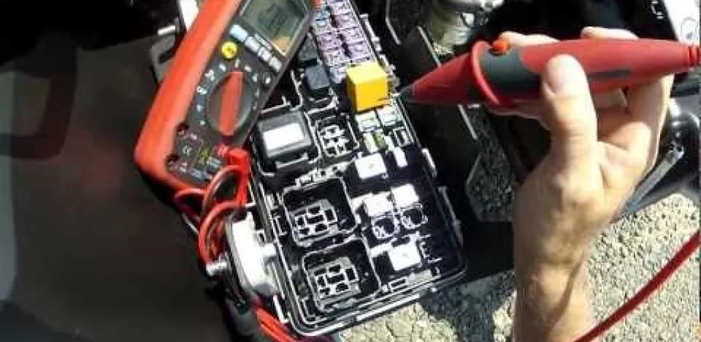
- Tools needed: digital multimeter, test lamp, 9-12V battery, jumper wires.
- Locate the relay by fuse box diagram; inspect visually; test coil resistance.
Electrical system problems in modern cars are often caused by faulty relays. These essential components control everything from headlights and climate control to the fuel pump and radiator fan. While diagnosing electrical issues can seem intimidating, testing relays is a procedure accessible to hobbyist mechanics.
Relays function like smart switches, allowing a low-current control circuit to energize or de-energize a higher-current circuit. This separation protects sensitive components and prevents overheating and damage to the electrical system.
What is a relay and how does it work
Auto relays are electromagnetic devices found in almost all modern vehicles, and they’re also used in maritime or aerospace applications. Their operating principle is based on separating circuits: a low-current control circuit energizes an electromagnet that closes or opens the contacts of a high-current power circuit.
Practical examples of use
Imagine your car’s headlights — if you connected them directly to the dashboard switch, the high current could exceed the switch’s capacity, causing wires to overheat or even start a fire. A relay lets a small button on the dashboard safely control high-current consumers.
Relays can simultaneously control multiple systems, such as:
- Starting system (main relay)
- Headlights (high beam relay, low beam relay)
- Cooling fan
- Fuel pump
- Air conditioning compressor
- Horn
Essential safety measures
Before you start testing, follow these safety rules:
To prevent damage:
- Never replace a relay with a random one — the wrong relay can cause short circuits
- Check exact specifications (amperage, voltage, contact type)
- Consult the diagram in the fuse box
For personal safety:
- Never work in the presence of flammable gases
- Avoid modifying or repairing damaged relays
- If the relay shows signs of burning, inspect the wiring as well
- Always refer to the service manual for the correct identification
Tools needed for testing
For a full relay test you’ll need:
- Digital multimeter (with Ohm and DC Volt functions)
- Test lamp or bulb with leads
- 9-12V battery for power
- Vehicle service manual
- Jumper wires for temporary connections
How to test a relay step by step

Step 1: Locating the relay
Most relays are located in the fuse box in the engine bay or under the dashboard. Identify the faulty relay using:
- The diagram stuck on the fuse box cover
- The vehicle service manual
- Symptoms of the issue (for example, the cooling fan won’t start = fan relay)
Step 2: Visual inspection
Before testing, check:
- Connectors for corrosion or damage
- Relay housing for cracks or signs of burning
- Contact positions for dirt or oxidation
Step 3: Testing coil resistance
- Set the multimeter to the Ohm (Ω) function
- Identify the coil pins (consult the relay schematic)
- Measure resistance between the two coil pins
- Normal result: 50–120 Ω
- Abnormal result: 0 Ω (short) or OL/inf (coil open)
Step 4: Testing contacts at rest
- Keep the multimeter on Ohms
- Measure resistance between the switch contacts pins
- Normal result: OL or open (contacts open)
- Abnormal result: 0 Ω (contacts welded)
Step 5: Testing electromagnet operation
- Power the coil with a 9–12 V battery
- Important: on 4-pin relays, polarity does not matter
- On diode-relays, respect the marked polarity
- Normal sound: a distinct “click” when connected and disconnected
Step 6: Testing the contacts under load
- With the coil powered, connect the test lamp
- One lead of the lamp to a relay contact pin
- The other lead to ground
- Normal operation: the lamp lights when the coil is energized
- Fault: the lamp does not light or flickers
Step 7: Measuring voltage at the switch
- Set the multimeter to Volts DC
- With the coil powered, measure the voltage at the switch contacts
- Normal result: battery voltage (12 V)
- Voltage drop: damaged contacts
Step 8: Final resistance test
- Disconnect coil power
- Energize the coil again
- Measure the resistance of the closed contacts
- Functional relay: nearly 0 Ω across closed contacts
- At rest: OL across open contacts

Interpreting test results
Working relay
- Coil: 50–120 Ω
- Contacts at rest: open circuit (OL)
- Contacts energized: near 0 Ω
- Sound: distinct click
- Switching: fast and reliable
Defective relay — common signs
- Coil open: infinite resistance (OL)
- Coil shorted: very low resistance (<10 Ω)
- Contacts welded: circuit closed permanently
- Contacts burnt: high resistance in the closed position
- No sound: electromagnet nonfunctional
Consequences of ignoring a relay problem
A faulty relay can cause:
Immediate damage:
- Fuse blowing
- Overheating wiring
- Deterioration of controlled components
- Battery drain
Major risks:
- Fire in the engine bay
- Total electrical system failure
- Damage to car computers (ECUs)
- Very high repair costs
Practical problem examples:
- Faulty fuel pump relay = engine stalling
- Faulty cooling fan relay = engine overheating
- Faulty headlight relay = visibility and safety issues
Alternatives to testing with a multimeter
Substitution method
If you don’t have the necessary tools:
- Identify an identical relay from another circuit
- swap the relays
- Check if the problem moves
- Caution: only use relays with identical specifications
Simplified testing
Without tools you can:
- Listen for the “click” on actuation
- Feel for relay vibration with your finger
- Visually check for burn marks
- Inspect connections for corrosion
Locating relays in the vehicle
Common locations
- Under the hood: main fuse box
- Inside the cabin: dashboard, left side
- In the trunk: on some premium models
- Next to the battery: high-current relays
Identification by symptoms
- Does not start: main or starting relay
- Headlights not functioning: headlight relay
- Fan not starting: cooling fan relay
- AC not functioning: compressor relay
- Horn not sounding: horn relay
Consulting the service manual
The service manual is essential for:
Technical information
- Detailed wiring diagram
- Exact relay locations
- Technical specifications (amperage, type)
- Specific testing procedures
- Disassembly sequence
Model differences
- Each vehicle has unique specifications
- Even the same model can differ between years
- Relay positions can vary
- Relay types can differ

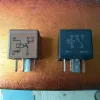
Types of car relays
By number of pins
- 4 pins: simple relay, most common
- 5 pins: with an extra contact
- Multipin: for complex functions
By function
- Standard relays: for ordinary loads
- Timed relays: with activation delay
- Diode relays: for circuit protection
By power
- Small relays: up to 20 A
- Medium relays: 20–40 A
- Large relays: over 40 A
Replacement costs
Relay prices vary considerably:
Standard relays:
- Simple relays: 15–50 RON
- OEM relays: 50–150 RON
- Aftermarket relays: 20–80 RON
Special relays:
- Timed relays: 80–200 RON
- Smart relays: 150–500 RON
- Premium original relays: 200–800 RON
Factors influencing price:
- Vehicle make and model
- Relay complexity
- Manufacturer (OEM vs aftermarket)
- Availability on the market
Preventive maintenance
To prevent relay failure:
Regular checks
- Clean connections once a year
- Visual inspection for corrosion
- Functional testing at service
Wear-accelerating factors
- Excess humidity
- Strong vibrations
- Overvoltage in the network
- Extreme temperatures
Early warning signs
- Intermittent operation
- Abnormal sound on actuation
- Delayed response
- Overheating
Testing relays is a fundamental diagnostic procedure for automotive electrical problems. With the right tools and adherence to safety procedures, any vehicle owner can identify and resolve these common issues, saving time and money at the service shop.