- P0340 indicates the PCM detected incorrect camshaft sensor voltage or waveform.
- Symptoms include hard starting, unstable idle, poor acceleration, and reduced performance.
- Common causes are fluid contamination, electrical problems, and mechanical faults.
- In some vehicles, crankshaft sensor failure can trigger P0340.
The P0340 error code is one of the more common faults seen in modern vehicles, being directly linked to the camshaft position sensor. This issue can significantly affect engine performance and requires a methodical approach to diagnosing and repairing it. Understanding this code and its implications is essential for any car owner or auto mechanic.
The camshaft position sensor plays a crucial role in the engine’s proper operation, controlling ignition timing and fuel delivery for each cylinder.
What the P0340 error code means
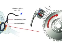
The PCM (Powertrain Control Module) has detected an incorrect voltage reading or an abnormal waveform shape from the camshaft position sensor circuit. The camshaft position sensor is an electromagnetic sensor that works in concert with the reluctor ring or gear on the camshaft. The notches on the camshaft interrupt the magnetic field of the sensor (as perceived by the PCM) to provide precise data on camshaft position. This data is vital for accurately calculating fuel delivery and ignition timing.
P0340 activation parameters
Deviations in the reference system voltage exceeding 10% of the manufacturer-specified reference value can trigger the code and illuminate the on-board warning light, indicating a fault. These deviations are perceived by the PCM as an incorrect camshaft position.
The system continuously monitors the sensor signal and compares the received values to programmed parameters. Any significant deviation from these parameters will trigger the P0340 code.
Symptoms of the P0340 OBD2 error code
The manifestations of this code can vary in intensity, from minor issues to complete engine failure:
- Hard starting: Delayed engine start or extended cranking
- Unstable idle: Engine hunts at idle or shows irregular idle speed
- Poor acceleration: Weak throttle response or loss of power
- Overall reduced performance: Increased fuel consumption and reduced performance
- Engine won’t start: In extreme cases, the engine may fail to start altogether
- Erratic operation: Misfiring or erratic running
Common causes of the P0340 code
Fluid contamination
The most common cause of this code is contamination from engine oil or other fluids that have leaked onto sensors, wiring, or electrical connectors. This contamination can cause:
- Damaged, torn, or shorted connections
- Loose or shorted electrical connectors
- Sensors operating improperly due to fluid contamination
Electrical problems
- Damaged or corroded wiring
- Faulty electrical connectors
- Ground or power supply issues
- Short circuits in the wiring harness system
Mechanical faults
- Faulty camshaft position sensor
- Issues with the reluctor ring (toothed ring) on the camshaft
- Excessive wear of the camshaft
- Timing issues in the engine
Important note
In some vehicles, the system stores a camshaft position sensor circuit code if the crankshaft position sensor is defective. In these cases, replacing both position sensors is recommended to avoid future problems.
Common diagnostic mistake
Warning: Immediately replacing the camshaft position sensor is the most common incorrect move seen in practice. This code refers to the entire camshaft position sensor circuit, not just the sensor itself.
It is crucial not to replace the sensor before performing a detailed diagnostic of the entire system. A rushed approach can lead to unnecessary costs and unresolved underlying issues.
The P0340 diagnostic process
Operating principle
The camshaft position sensor is an electromagnetic sensor that interacts with a metal reluctor ring (or gear) at one end or the other of the camshaft. Engines that use multiple camshafts (dual-cam engines) are equipped with several camshaft position sensors.
As the reluctor passes by the sensor, a notch or gap in the teeth interrupts the wave pattern sent by the sensor to the PCM. This interruption correlates with a reference value for the programmed ignition timing in the PCM.
Tools required for diagnosis
For a correct and complete diagnosis you will need the following specialized tools:
- Professional OBD2 scanner
- Digital multimeter (voltmeter/ohmmeter)
- Oscilloscope for waveform analysis
- Vehicle-specific service manual
Diagnostic steps
1. Initial visual inspection
Always start with a thorough visual inspection of all cables and connectors in the camshaft position sensor system:
- Check cable insulation integrity
- Inspect connectors for corrosion or damage
- Look for traces of fluids (oil, coolant, power steering fluid)
- Verify proper connector mounting
2. Preliminary repairs
Repair or replace damaged, disconnected, shorted, or corroded wiring, connectors, and components as applicable. Always re-test the system after repairs to ensure the intervention’s success.
3. Error code scanning
If all wiring, connectors, and components (including fuses) appear in order, connect the scanner to the diagnostic port and record all stored codes. This information can be very useful in diagnosing intermittent conditions that may have contributed to storing this code.
4. Testing under real conditions
After clearing the codes, start and drive the vehicle to see if the code reappears. If the code does not return immediately, you may be dealing with an intermittent condition.
Managing intermittent conditions
Intermittent conditions can be challenging to diagnose and, in extreme cases, may worsen the situation before a proper diagnosis. For these situations:
Using an oscilloscope
Use an oscilloscope to monitor the waveform patterns created by the distributor, camshaft, and/or crankshaft sensors. Specifically look for:
- Suspect areas of circuits contaminated with oil, coolant, or power steering fluid
- Worn or damaged insulation on cables
- Abnormal fluctuations in sensor signals
Detailed electrical testing
If no obvious circuit issues are found:
- Perform a resistance test on the camshaft position sensor
- Perform a voltage test on the sensor connector
- Compare results with the reference voltage specified by the manufacturer
Interpreting the results
- If the reference voltage readings are within specification but the sensor resistance readings do not match: replace the camshaft position sensor and the crankshaft position sensor
- If the voltage readings do not match the specified reference values: check circuit continuity using a digital multimeter
Important diagnostic precautions
Be cautious when testing the PCM wiring: Be very careful when checking resistance values on wiring connected to the PCM. For optimal results, disconnect the PCM electrical connector before using a multimeter on the wiring side of the circuit.
Note: A PCM failure is possible but extremely rare. Do not assume a faulty PCM until all other possibilities have been ruled out.
Costs and repair recommendations
Estimated costs
- Camshaft position sensor: 100-300 RON (depending on vehicle make)
- Diagnostic labor: 150-250 RON
- Wiring repairs: 50-200 RON (dependent on the problem scope)
Prevention recommendations
- Regular maintenance: Periodic engine oil changes to prevent contamination
- Periodic inspections: Check wiring and connectors
- Use of genuine parts: For maximum reliability
- Professional diagnostics: At the first signs of trouble
The P0340 code may seem complex, but with a methodical approach and the right tools, most issues can be resolved efficiently. The key to success is performing a thorough diagnostic before replacing any components.