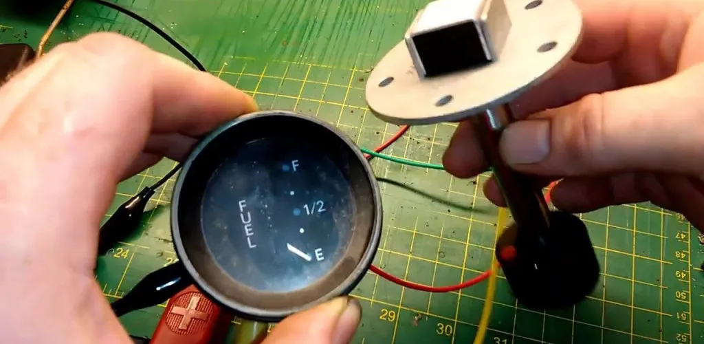
- Fuel gauge uses a float sender, wiring, and a dash gauge.
- After refueling, the gauge may overshoot Full for 5–10 km.
- Inclines cause temporary readings as fuel shifts.
- Sender unit faults include worn float arm and damaged float.
The fuel gauge is a crucial element of any vehicle’s instrumentation, especially for drivers covering long distances or those who forget to monitor fuel consumption. Although it seems simple, there are occasions when the gauge no longer displays the correct fuel level, turning a routine trip into a stressful experience. This issue can have unpleasant consequences, from being stranded on a busy road to damaging the fuel pump due to running the pump dry.
Understanding the causes that lead to this fault and knowing how to fix them can save time, money and nerves. In the following sections, we explore in detail the four main causes of this problem and the available solutions.
How the Fuel Gauge Works
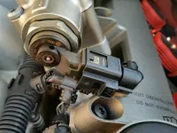
The Fuel Sender Unit
This is the most complex component, integrated into the fuel supply module:
- Float: A lightweight part (usually plastic or foam) that floats on the surface of the fuel
- Metal arm: A rod that connects the float to the sensor, made from corrosion-resistant materials
- Position sensor: A potentiometer or Hall effect sensor that converts mechanical movement into an electrical signal
- Auxiliary components: The fuel pump, the primary filter and electrical connections
Electrical Transmission Circuit
This circuit carries the electrical signal from the sensor to the gauge on the dash, including:
- The main wiring harness with dedicated wires
- Protection fuses
- Control relays (if applicable)
- The engine control module (ECM) in modern vehicles
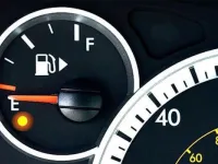
Dashboard Gauge
The gauge on the instrument cluster may be analog (dial) or digital, displaying the level via:
- Dial graduations on the gauge
- Lighted bars
- Numeric display on premium vehicles
Normal Operation vs. Fault Scenarios
Situations that Look Like Faults but Are Normal
After a full refuel: The gauge may temporarily overshoot the “Full” mark due to the pressure of freshly added fuel. The float needs 5–10 kilometres to settle into the correct position, because it isn’t mounted exactly at the bottom of the tank.
When the tank seems empty: When the gauge shows zero, there are typically 5–10 litres left in the tank. This safety margin helps prevent the pump from running dry, which can cause costly damage.
On an incline: On an uphill slope, fuel shifts toward the rear, making the gauge read lower. On a downhill slope, the effect is opposite. These fluctuations are temporary and normal.
The Four Main Causes of Malfunctions
1. Sender Unit Failure (Float)
This is the most common cause of problems with the fuel gauge.
Typical symptoms:
- The gauge stays stuck on “Empty” even after a full refuel
- Extreme and illogical fluctuations of the gauge while driving
- Completely erroneous readings that do not correlate with actual consumption
- The gauge jumps between extremes without an apparent reason
Technical causes:

- Wear on the float arm: Continuous vibrations and shocks can bend or break the metal arm
- Damaged float: Cracks in the material allow fuel to enter, causing the float to sink
- Faulty position sensor: Contacts in the potentiometer wear out or oxidize
- Corrosion: Exposure to fuel vapours and moisture damages metal components
- Deposits: Impurities in the fuel can settle on components, affecting function
2. Electrical Circuit Problems
The electrical system can be affected by a range of factors, from natural wear to manufacturing defects.
Specific symptoms:
- The gauge doesn’t move at all or remains at zero
- Intermittent operation, with correct readings followed by non-functioning periods
- Inconsistent readings that change without relation to the real level
Electrical causes:
- Blown fuses: Usually 10–15 A, can be affected by overloads
- Deteriorated connections: Oxidation or loosening at main connectors
- Damaged wiring: Broken, pinched or burnt wires due to engine heat
- Short circuits: From insulation wear or water ingress
- Grounding issues: Chassis connection to ground may be interrupted
3. Gauge Stuck on “Full”
A particular situation that can be especially hazardous for drivers.
Distinctive symptoms:
- The gauge remains permanently on the “Full” position
- No changes even after hundreds of kilometres
- It does not reset after turning the engine off and on
- Possible warning messages on the dash
Possible causes:
- Mechanical float jam: Could be caught by a tank component or deposits
- Wiring short: A shorted wire may continuously send the “full” signal
- Sensor failure: Internal contacts may be stuck in the minimum-resistance position
- Software issues: On modern vehicles, the control module may have erroneous data
4. Instrument Cluster Failure
On modern vehicles, this component is increasingly complex and prone to faults.
Systemic symptoms:
- Multiple gauges on the dash operate erratically
- The fuel gauge does not respond to autotest procedures
- Error messages on the central display
- Intermittent illumination of the instrument panel
Technical causes:
- Damaged integrated circuits: Electronic components can fail due to heat or wear
- Software issues: Corrupted firmware or incompatible versions
- Physical damage: Shocks, vibrations, or water ingress
- Power supply issues: Incorrect voltage or current fluctuations
Professional Diagnostic: Step by Step
Equipment and Tools Required
For a correct diagnosis, you will need:
- A digital multimeter with DC and resistance measurements
- An OBD II scanner compatible with the vehicle brand
- An oscilloscope for advanced signal analysis (optional)
- The electrical diagram specific to the vehicle model
- A tool kit with wrenches and screwdrivers
- The service manual with technical specifications
Diagnostic Procedure
Step 1: Preliminary Check
Visual inspection:
- Check the condition of fuses dedicated to the fuel system
- Visually inspect accessible connectors
- Observe the gauge behavior at engine start
Functional test:
- Run the instrument cluster self-test (procedure varies by brand)
- Note whether the gauge responds to test commands
- Check for error codes on the dash display
Step 2: Scan with an OBD II Scanner
Real-time data:
- Connect the scanner and access engine parameters
- Look for “Fuel Level” or “Tank Level” in live data
- Compare the scanner reading with the dashboard gauge
- Record any error codes (DTC)
Interpreting results:
- If the scanner shows correct readings but the gauge does not: the issue is with the display
- If both readings are wrong: the problem lies in the sensor
- If there is no data: the issue is in the electrical circuit
Step 3: Advanced Electrical Testing
Power supply:
- Measure the voltage at the sensor connector (should be 5 V or 12 V)
- Check continuity of the grounding circuit
- Verify the integrity of the main wiring harness
Sensor testing:
- With the tank below half for safety, disconnect the sensor
- Measure sensor resistance across different simulated positions
- Check whether values conform to the manual specifications
- Test stability of values over time
Step 4: Inspection of Physical Components
Accessing the sender unit in the tank:
- CAUTION: This operation requires special safety measures
- Partially drain the tank
- Disconnect the battery
- Ventilate the work area
Inspection of the float:
- Check the physical integrity of the float
- Inspect the metal arm for bends
- Test the freedom of movement of the assembly
- Check the cleanliness of the components
Repair Solutions After Diagnostics
For Simple Electrical Issues
Basic repairs:
- Replacing blown fuses with ones of the same rating
- Cleaning corroded connections with a spray contact cleaner
- Repairing damaged wires with proper welding and insulation
- Tightening loose connections and applying dielectric grease
For Float Faults
Repair options:
- Complete replacement: The safest solution for complex problems
- Partial repair: Possible only for slightly bent arms
- Professional cleaning: For problems caused by deposits
Technical considerations:
- Use only original or high-quality equivalent parts
- Follow the specified torques for tightening
- Calibrate after installation (if required)
For Instrument Cluster Problems
Available solutions:
- Software reprogramming: At authorized dealers with specialized equipment
- Complete replacement: For irreversible hardware faults
- Specialized repair: At firms that focus on automotive electronics
Important aspects:
- Proper programming of the new unit with the vehicle parameters
- Synchronization with other vehicle modules
- Check compatibility with the car’s software version
Preventive Measures and Maintenance
Recommendations for Drivers
Driving habits:
- Avoid driving with the tank below 1/4
- Fuel at known stations for fuel quality
- Monitor consumption to detect unusual changes
- Do not ignore engine management warnings
Preventive maintenance:
- Replace the fuel filter according to the manufacturer’s schedule
- Periodically use quality additives to clean the system
- Have computerized diagnostics performed at maintenance services
- Regularly verify the operation of all dashboard instruments
For Technical Maintenance
Regular checks:
- Visual inspection of accessible electrical connections
- Test system operation with seasonal changes
- Monitor error codes via OBD scan
- Check the sealing of the fuel supply system
When to Call a Specialist
Although preliminary diagnosis can be done by the owner, there are situations where specialist intervention is mandatory:
Situations that require service:
- Any work involving opening the fuel tank
- Replacing or reprogramming the instrument cluster
- Complex wiring issues requiring electrical diagrams
- When diagnosis exceeds your knowledge or available equipment
- For calibrating the system after major repairs
Safety measures:
- Do not smoke and do not use tools that produce sparks near the fuel system
- Ensure adequate workspace ventilation
- Disconnect the battery before any electrical work
- Use personal protective equipment
Cost Estimates for Repairs
Parts and Labor
- Fuses and consumables: 20–100 RON
- Float sensor (aftermarket): 200–500 RON
- Original float sensor: 400–800 RON
- Diagnostic labor: 100–200 RON
- Sensor replacement labor: 300–600 RON
- Wiring repairs: 150–500 RON
- Aftermarket instrument cluster: 800–2000 RON
- Original instrument cluster: 1500–3000 RON
- Programming/coding: 200–500 RON
Factors Influencing Costs
- Vehicle make and model
- Availability of parts on the market
- Complexity of accessing the components
- Need for specialized equipment
- Service pricing policy
A faulty fuel gauge may seem like a minor issue, but it can have significant safety and driving comfort implications. Correct diagnosis and professional repair ensure optimal system function and prevent unpleasant situations on the road. Investing in repairs now pays off by avoiding the stress and extra costs associated with possible fuel supply interruptions.