- P0119 means intermittent ECT circuit voltage deviations detected by the PCM.
- Voltage variation exceeding 10% triggers MIL and P0119.
- MIL on, rough idle at cold, hard starting, and increased fuel use.
- Causes include electrical issues (corroded/damaged connectors, loose wiring) and mechanical faults (low coolant, air pockets).
The P0119 error code is one of the most common issues related to the engine coolant temperature sensor (ECT). This error indicates an intermittent problem in the ECT sensor circuit, which can affect engine performance and engine management efficiency.
What the P0119 code means
The P0119 code refers to an issue in the ECT sensor circuit that exhibits intermittent behavior. This code indicates that the Powertrain Control Module (PCM) has detected a voltage reading from the ECT sensor or its circuit that deviates from the normal operating parameters.
The engine control module continuously monitors signals from the temperature sensor, and when it detects improper variations, it stores this trouble code to inform the technician about the existing issue.
P0119 parameter thresholds
The engine temperature sensor circuit voltage that exceeds manufacturer reference variations by more than 10% will trigger a P0119 code. When this condition is detected, the Malfunction Indicator Lamp (MIL) on the vehicle dashboard lights up, indicating a fault in the engine management system.
This 10% tolerance is set by the vehicle manufacturer and may vary slightly depending on the model and make of the car, but the operating principle remains the same for most modern vehicles.
Symptoms of the P0119 code
When the P0119 code appears, the driver will typically notice the following symptoms:
- MIL (Malfunction Indicator Light) illuminated on the dashboard
- Rough engine operation at low temperatures
- Difficult engine starting, especially in cold weather
- Increased fuel consumption due to incorrect engine mapping
- Engine overheating in extreme cases
- Climate control ventilation may operate abnormally
Common causes for the P0119 code
Electrical problems
- Corroded or damaged ECT sensor electrical connector
- Broken or damaged wiring in the sensor circuit
- Loose connections at the connectors
- Short circuits in the wiring harness
Mechanical faults
- Faulty ECT sensor due to wear or internal damage
- Low coolant level affecting temperature readings
- Air pockets in the cooling system interfering with measurements
Rare issues
- Faulty PCM (very rare, but possible)
- Vehicle grounding issues
Common misdiagnosis
One of the most frequent errors in diagnosing this code is assuming the ECT sensor is automatically defective. In reality, the problem can be caused by:
- Broken or corroded electrical wires not visible at first glance
- Confusion between sensors – many modern vehicles use separate sensors for the dash display and for PCM inputs
- Replacing the wrong sensor which can worsen the problem
- Neglecting the cooling system check before replacing components
Diagnostic guide for the P0119 code
Understanding the ECT system
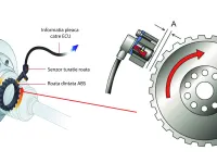
The engine is equipped with a temperature sensor (usually a resistance-type sensor with two or three wires) that provides data to the PCM. The sensor typically has:
- A power supply wire (usually a 5-volt reference signal)
- A ground wire to complete the circuit
- A signal wire (in the case of 3-wire sensors)
Operating principle
The PCM uses the reference voltage wire to monitor engine temperature through a simple principle:
At high temperatures:
- Sensor resistance decreases
- Reference voltage increases
- PCM interprets this as high temperature
At low temperatures:
- Sensor resistance increases
- Reference voltage decreases
- PCM interprets this as low temperature
Step-by-step diagnostic procedure
Step 1: Check the cooling system
Before any other tests, verify:
- Coolant level in the reservoir and radiator
- Coolant color and condition
- Presence of air bubbles in the system
- Cooling fan operation
Step 2: Test for serious problems
If the vehicle has run hot, perform:
- Preventive chemical block test to detect hydrocarbons in the cooling system
- Cooling system pressure test to identify leaks
- Thermostat and water pump check
Step 3: Electronic diagnostics
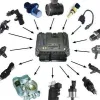
Equipment needed:
- OBD2 scanner or code reader
- Digital multimeter
- Manufacturer electrical schematic
- Thermometer for real temperature verification
Testing procedure:
-
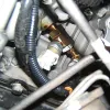
Visual inspection
- Check all cables and connectors for damage
- Look for signs of corrosion, breaks, or burns
- Repair any visible faults
-
Connect the scanner
- Record all stored codes
- Check real-time data from the ECT sensor
- Compare with the actual engine temperature
-
Test the reference voltage
- With the ignition on, verify the presence of the reference voltage (5V)
- Check the continuity of the ground wire
- Verify that the signal varies with temperature
-
Test the sensor resistance
- Disconnect the sensor
- Measure resistance at different temperatures
- Compare with the manufacturer’s specifications
Step 4: Intermittent-condition testing
For intermittent issues:
- Test under variable temperature conditions
- Vibration testing to detect loose contacts
- Monitor over extended periods with the scanner connected
- Check the influence of other electrical consumers
Repair procedures
For electrical problems
- Repair or replace damaged wiring
- Clean and protect corroded connectors
- Ensure firm contacts at all connections
For sensor problems
- Replace the ECT sensor if tests confirm failure
- Use OEM parts or equivalent quality
- Apply thermal compound if specified
For system issues
- Top up coolant level
- Bleed air from the cooling system
- Replace defective cooling system components
Finalizing the repair
After performing the repairs:
- Clear the diagnostic trouble codes (DTCs) with the scanner
- Start the engine and bring it to its operating temperature
- Monitor for recurrence
- Test under real driving conditions
Important: If all components and circuits are in good condition and the problem persists, it may be necessary to check or replace the PCM. However, PCM failures are rare and replacement requires specialized reprogramming.
Preventing future issues
To avoid a recurrence of this error:
- Perform regular cooling system maintenance
- Periodically check coolant level and quality
- Protect wiring from moisture and extreme temperatures
- Replace coolant according to the recommended intervals