- P0133 indicates upstream oxygen sensor Bank 1 Sensor 1 circuit issue.
- Rough idle and power loss; increased fuel consumption.
- Causes include sensor wear, lead contamination, silicon contamination, thermal shock.
- Electrical checks: resistance ~8 ohms; voltage 12.6–13.8 V; constant readings >8s trigger.
The OBD2 P0133 fault code refers to a fault in the oxygen sensor circuit for Bank 1 Sensor 1 (upstream sensor). This error appears when the oxygen sensor (lambda) sends a voltage signal that does not fall within the normal parameters set by the ECU, causing the engine management system to store a fault code and, in some cases, illuminate the warning light on the dashboard.
To fully understand this issue, it is important to know the crucial role the oxygen sensor plays in the engine’s optimal operation. These sensors continuously monitor the oxygen level in the exhaust gases to allow the ECU to precisely adjust the air–fuel mixture.
What P0133 Code Means
The structure of the P0133 code provides precise information about the location of the problem:
- B1 represents Bank 1 (the first engine bank in V-configurations) or the single bank in a non-V engine
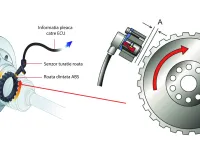
- S1 indicates Sensor 1, also known as the upstream sensor, located before the catalytic converter
This sensor is responsible for monitoring the exhaust gas composition entering the catalytic converter, providing the feedback needed for precise fuel injection control.
Technical parameters and code setting
Heated oxygen sensor operates within certain technical parameters:
Electrical resistance
- The normal resistance level for the heating circuit is approximately 8 ohms
- Variations greater than ±10% in either direction will trigger the P0133 code“
- This strict tolerance ensures the system functions optimally
Supply voltage
- The heating circuit operates at battery voltage (roughly 12.6–13.8 V)
- Variations exceeding ±10% from this standard will initiate the fault code
- Power is supplied through a protected circuit
Response time
- Under normal closed-loop operation, the sensor should oscillate consistently
- Readings that remain constant for more than 8 consecutive seconds will trigger the P0133 code
- This characteristic indicates the sensor’s ability to respond rapidly to changes in the exhaust gas
Specific symptoms of the P0133 code
When the P0133 code appears, drivers may notice the following manifestations:
Reduced engine performance
- Rough running at idle
- Power loss, especially under acceleration
- Delayed throttle response
- Abnormal engine vibrations
Fuel economy and emissions issues
- Increased fuel consumption by 15–30%
- Visible black smoke from the exhaust
- Elevated pollutant emissions
- Failure at the emissions test (ITP)
Visual indicators
- Check Engine light illuminated on the dashboard
- Error messages on the instrument cluster display
- In severe cases, operation in a limp mode
Common causes of the P0133 fault
Oxygen sensor failures
- Natural wear: Oxygen sensors have a service life of roughly 100,000–150,000 km
- Lead contamination: Use of leaded fuels permanently damages the sensor
- Silicon contamination: Silicon particles from oils or antifreeze can affect operation
- Thermal shock: Extreme temperature variations can damage the ceramic element
Electrical problems
- Corroded connectors: Moisture and road salt affect connectors
- Damaged wiring: Broken wires or compromised insulation
- Short circuits: Unintended contact between wires
- Blown fuses: Power circuit protections
Fuel system issues
- Incorrect fuel pressure: Defective pump or regulator
- Dirty or blocked injectors: Affect the air–fuel mixture
- Clogged air filter: Changes the air–fuel ratio
Rare ECU problems
- Hardware failures: Internal electronic component damage
- Software errors: Incorrect parameter calibrations
- Electromagnetic interference: From other electronic systems
Common diagnostic mistakes
Premature sensor replacements
Many technicians default to replacing the oxygen sensor at the first sign of engine performance issues without a full diagnostic. This can lead to:
- Unnecessary costs for the vehicle owner
- The real problem remaining unsolved
- Further component damage down the line
Ignoring secondary causes
- Neglecting checks of wiring and connectors
- Skipping fuel system tests
- Not verifying the air intake and filter condition
Detailed diagnostic procedure
Visual inspection (preliminary)
The first step in diagnosing the P0133 code involves a thorough visual inspection:
Wiring and connectors
- Check wire integrity for cracks, wear, or signs of overheating
- Inspect connectors for corrosion, oxidation, or loose connections
- Trace wiring routes to ensure they do not rub against other components
Associated components
- Check the air filter condition – a clogged filter affects the mixture
- Inspect the exhaust system for leaks that can skew sensor readings
- Check the power circuit fuses and relays
Using diagnostic equipment
OBD-II scanner
- Connect the scanner to the diagnostic port
- Record all stored fault codes to identify related issues
- View live data to observe real-time parameters
- Analyze freeze frame data to understand the conditions when the error occurred
Digital multimeter
- Measure the supply voltage at the sensor connector
- Test the resistance of the heating circuit (should be ~8 ohms)
- Check the continuity of signal and ground circuits
Sensor functional testing
Test conditions
- The engine must be at normal operating temperature (80–90°C)
- ECU should be in closed-loop mode
- Testing should be performed at idle and under load
Normal parameters
- The sensor should oscillate between 100–900 millivolts
- Oscillation frequency should be at least 1 Hz
- Response time to changes should be under 100 milliseconds
Testing electrical circuits
Heating circuit
- Disconnect the sensor connector
- Measure the supply voltage (should be nearly battery voltage)
- Test the internal heater resistance of the sensor
- Check ground circuit continuity
Signal circuit
- Test the impedance of the signal circuit
- Check for electrical interference or noise
- Measure the reference voltage from the ECU
Repair procedure
Replacing the oxygen sensor
Preparation
- Allow the engine to cool completely
- Safely raise the vehicle
- Locate the faulty sensor using the electrical diagram
Removal
- Disconnect the wiring harness
- Use a dedicated oxygen sensor wrench
- Apply penetrating oil if the sensor is seized due to corrosion
- Remove carefully to avoid damaging the threads
Installing the new sensor
- Apply anti-seize paste to the threads
- Tighten to the specified torque (typically 30–50 Nm)
- Reconnect the wiring harness
- Verify the connection is correct
Repairing electrical problems
Damaged wiring
- Replace affected sections with wires of the same specification
- Use sealed connectors and heat-shrink tubing
- Ensure wiring routes do not interfere with moving components
Corroded connectors
- Clean contacts with contact cleaner spray
- Apply dielectric grease for protection
- Replace connectors that are severely damaged
Final verification
Functional test
- Clear all fault codes
- Start the engine and bring it to operating temperature
- Perform a test drive to verify normal operation
- Rescan the system to confirm the absence of errors
Estimated costs and labor time
Parts costs
- OEM oxygen sensor: 300–800 RON
- Aftermarket sensor: 150–400 RON
- Wiring repair: 50–150 RON
- Connectors: 20–80 RON
Labor time
- Complete diagnostic: 1–2 hours
- Sensor replacement: 30 minutes – 1 hour
- Wiring repair: 1–3 hours (depending on problem extent)
Preventing future issues
Regular maintenance
- Replace the oxygen sensor according to the service schedule
- Use only high-quality fuel
- Regularly replace the air filter
- Clean the injection system as part of maintenance
Monitoring
- Periodically check warning lights
- Watch for changes in fuel consumption
- Note any changes in engine behavior
The P0133 code is a common but serious issue that requires prompt attention. A correct diagnosis and proper repair will restore engine performance and reduce pollutant emissions, contributing to long-term optimal operation.